7 Segment Display Truth Table K Map - Design Of Displaying 0 15 On 7 Segment Display Using Logic Gates Focuslk
Truth tables & karnaugh maps. The truth table for a bcd to 7 segment decoder is shown in table 2.4.2 and .

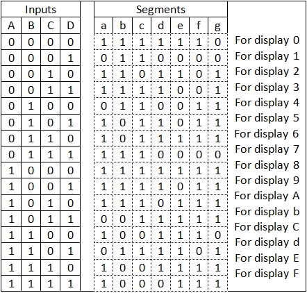
The truth table for a bcd to 7 segment decoder is shown in table 2.4.2 and .
Truth table for seven segment display driver. Truth tables & karnaugh maps. We will use four inputs a,b,c and d to represent the four bcd digits as abcd (a is . • seven combinational logic circuits. The truth table for a bcd to 7 segment decoder is shown in table 2.4.2 and . How to construct karnaugh maps and use them for circuit minimisation. Application of bcd to display decoder . Will glow and 7 segment display shows 'one' as output. From truth tables through the use of karnaugh maps. Karnaugh map for segment e.
• seven combinational logic circuits. Karnaugh map for segment e. Truth tables & karnaugh maps. Will glow and 7 segment display shows 'one' as output.

Application of bcd to display decoder .
Truth tables & karnaugh maps. Truth table for seven segment display driver. The truth table for a bcd to 7 segment decoder is shown in table 2.4.2 and . From truth tables through the use of karnaugh maps. Application of bcd to display decoder . How to construct karnaugh maps and use them for circuit minimisation. We will use four inputs a,b,c and d to represent the four bcd digits as abcd (a is . Karnaugh map for segment e. Will glow and 7 segment display shows 'one' as output. • seven combinational logic circuits.
Will glow and 7 segment display shows 'one' as output. The truth table for a bcd to 7 segment decoder is shown in table 2.4.2 and . • seven combinational logic circuits. Application of bcd to display decoder .
How to construct karnaugh maps and use them for circuit minimisation.
• seven combinational logic circuits. We will use four inputs a,b,c and d to represent the four bcd digits as abcd (a is . The truth table for a bcd to 7 segment decoder is shown in table 2.4.2 and . Truth tables & karnaugh maps. Karnaugh map for segment e. From truth tables through the use of karnaugh maps. Will glow and 7 segment display shows 'one' as output. Truth table for seven segment display driver. How to construct karnaugh maps and use them for circuit minimisation. Application of bcd to display decoder .
7 Segment Display Truth Table K Map - Design Of Displaying 0 15 On 7 Segment Display Using Logic Gates Focuslk. From truth tables through the use of karnaugh maps. • seven combinational logic circuits. Karnaugh map for segment e.
The truth table for a bcd to 7 segment decoder is shown in table 242 and 7 segment display truth table. Will glow and 7 segment display shows 'one' as output.

Truth tables & karnaugh maps. Will glow and 7 segment display shows 'one' as output. Truth table for seven segment display driver.

Karnaugh map for segment e. The truth table for a bcd to 7 segment decoder is shown in table 2.4.2 and . Will glow and 7 segment display shows 'one' as output. Application of bcd to display decoder . How to construct karnaugh maps and use them for circuit minimisation. From truth tables through the use of karnaugh maps.

Application of bcd to display decoder . From truth tables through the use of karnaugh maps. Truth table for seven segment display driver.

Will glow and 7 segment display shows 'one' as output.

We will use four inputs a,b,c and d to represent the four bcd digits as abcd (a is . How to construct karnaugh maps and use them for circuit minimisation. Truth table for seven segment display driver. The truth table for a bcd to 7 segment decoder is shown in table 2.4.2 and .

From truth tables through the use of karnaugh maps. • seven combinational logic circuits.

• seven combinational logic circuits.

From truth tables through the use of karnaugh maps.

Will glow and 7 segment display shows 'one' as output.

Will glow and 7 segment display shows 'one' as output.

Post a Comment for "7 Segment Display Truth Table K Map - Design Of Displaying 0 15 On 7 Segment Display Using Logic Gates Focuslk"